I talked about my initial lessons learned from low current measurement in
this post, but in this post, I want to focus more on the ground isolation problem in current measurement, arising from a collaboration from
Marcos, a EE friend of mine.
DUT (device under test)
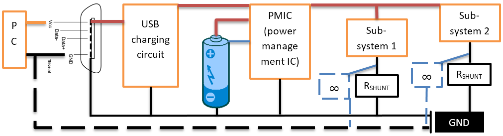
The focus of current measurement in a mobile system like a phone is when the system runs on battery. Of course such a system should be charged regularly (from USB for all mobile devices I am concerned with), so such a system can be viewed like this:
Always remember that it's the PMIC that supplies current to the system, rather than the battery itself; a lithium-ion battery actually has thermistor output (the blue wire in the above diagram) and some charging circuit inside, which the PMIC actually looks for, so if you insert a plain AA battery, PMIC might not turn on the voltage to the rest of the system.
When measuring current, I cab insert a shunt resistor in one of the red or the black lines above, and measure the voltage drop across that resistor (ΔV = Vh - Vl), like this:
If Rshunt (shunt resistor) is inserted in the red line above, it is called the high side shunt resistor, and if placed on the black line, it is called the low side shunt resistor. For the high side measurement case, Vh may stay roughly constant. But according to the Ohm's law, Vl will change according to the current flow: the higher the current, the lower Vl will be, as shown below, where the cursors A1 and A2 mark a current spike event:
If Rshunt is relatively large, the system downstream of the Rshunt sees a noticeable voltage swing in the supply current. Some components are relative intolerant of such voltage swing, and the system may not operate correctly. Therefore, I have to keep Rshunt small (< 1 Ohm). But since the current is tiny and Rshunt has to be a small, ΔV is small: typically << 10 mA. An average hand-held multi-meter CANNOT measure such tiny voltage, but expensive multi-meter like this can.
Clamp-style current meters can measure current just with magnetic field induced by current flowing in a wire, so that I don't have to cut existing circuit and I don't have to worry about the ground isolation (see below). BUT:
- In a tiny mobile system, it is difficult to put a huge clamp around tiny wires.
- The currents are on the order of uA and at most a few mA, and finding a reasonably priced yet sensitive clamp current meter that will work in this range is difficult.
Compelling need for ground isolation
Another reason that professional desktop multi-meters are expensive a lot of money for multi-meter is that the ground is isolated from the wall. Let's modify the original block diagram with a shunt resistor and a multi-meter measuring across it (represented as an idealized infinite resistance below), and also connect the unit to a USB power source, such as a PC:

When I connect the multi-meter, the Vl junction of Rshunt is now connected to the multi-meter's negative terminal. IF that negative terminal is grounded to the wall, then Vl is now tracking the wall ground--and that is OK so far, because the system GND (negative terminal of the battery) can just be lower potential than the wall ground (we are only talking about a few volts difference at most, so that we don't have to talk about ESD). But if I connect another ground--such as the USB current source--to the GND, I have introduced a ground loop. I's quite easy to forget this and damage the circuit. Isolated negative terminal of the multi-meter protects against this sin.
Ground isolation is also necessary if I want to measure current across more than 1 shunt resistor. Suppose I want to measure the digital and analog portion of the system separately, both on the high side. Since the Vl for the digital and analog portions will be at different potentials, the negative terminals of the multi-meter connecting to the Vl_d and Vl_a MUST NOT be connected. Unfortunately, most reasonable instruments share the negative terminal of ALL channels--to its power supply ground no less, so you cannot avoid the ground loop in that case.
Measuring on the lower side is only slightly better
To some extent, I can work around the ground loop problem by putting ALL Rshunt on the lower side, as illustrated below:
Measuring on the low side does NOT relieve us from the need to have a common ground across all negative terminals connected to the system; only proper ground isolated instruments can do that. In the above picture, I am running the virtual scope on the same PC that is also charging the DUT over USB. If I used 2 different PC--one connected to the USB port, and the other serving at the virtual scope for measuring the voltage across the shunt resistors, a ground loop will result.