Dec 6, 2015

Meet the Cypress PSoC 4 BLE

WARNING: unfinished blog entry

About half year ago, I went to a seminar hosted by Arrow, where I received this nice development board, and interacted with the Bluetooth feature of the board.
The red baseboard is the generic development motherboard with peripherals (e.g. capacitive touch sensor array) and USB based emulator connection to the PC, and the smaller red daughter board is the CY8C427LQI0BL483 eval board.  The black board is the "BLE dongle" that runs the BLE host emulation FW, for the PC to act as the counter part (usually through the CySmart SW) of the red eval board, like this picture:

Until now, my only ARM experience has been on TI Stellaris (now called Tiva) which is ARM Cortex-M4 based, and  the Zedboard, which packs a dual core ARM Cortex-A9.  But the BLE Pioneer Kit runs on Cortex-M0, so I began to check out the low level details of the processor, by reading through my favorite real-time OS (of a sort): QP, which has an example port (of QP version 4.5.04) to ARM Cortex M0 on the LPCXpresso-1114 board.  In this blog entry, I port QP to the CY8CKIT-042-BLE, and implement Bluetooth "Find Me" device in QP.

Getting started with the PSoC creator--on virtualbox

Setting up PSoC Creator on virtualbox

Similar to the Xilinx Zynq, PSoC is is programmable logic device with a CPU on the same die.  Being configurable means that the SW runs on top of customized HW--even if it is one that has been stable for some time.  So the PSoC Creator's is like the Xilinx Vivado IDE: it creates/configures the HW.  It is a convenient IDE that runs only on Windows, so I need to run in a virtual machine.  Installing the whole (kitchen sink) PSoC BLE toolchain is easy, but takes a long time.  The biggest problem with developing an embedded target in a virtual machine is getting the virtualbox guest to see the development board's USB endpoints.   It took me half a day to figure out the following steps (reinstalling the virtualbox several times along the way): I (the Linux user running the virtualbox) must be in the "vboxuser" and "lp" group:

sudo usermod -aG vboxuser henry
sudo usermod -aG lp henry

Then I had to RESTART the PC, before I could see in the virtualbox USB settings window the following USB devices the on the pioneer baseboard:
If the toolchain has been correctly installed, the Windows device drives will be found automatically when the Windows virtual machine boots up the next time, as you can see here:
These devices should show up in the Windows Device Manager (Start --> right click on Computer --> Manage --> Device Manager):
  • Bluetooth Radios
  • Network adapters: PAN and RFCOMM Protocol TDI
  • Ports: KitProg USB-UART
  • USB controllers: KitProg
When I plug in the "BLE dongle", I get another KitProg USB-UART device (enumerated on COM4)), which the CySmart SW can automatically find, as you can see here:

Blinking an LED

The project will drive an LED with a PWM HW, available from the Cypress Component Catalog tab --> Digital --> Functions --> TCPWM mode (I could also search for this in the textbox).  Supply the clock, and drive a digital out pin from line_n as shown below:
Change the clock frequency to 1 kHz, and then rename the output pin to Red_LED.

Optionally, I can draw the rest of the LED circuit elements on the schematic, as shown below):
These off-chip components are available in the "Off-Chip" catalog tab, and do not have any down stream consequences for the PSoC creator.  [Q: what does "include in Netlist" do?]
To constrain the output pin to an actual pin on the chip, bring up the design wide resource wizard in the project explorer.  Remember that the PWM HW is INSIDE the chip, and constrain the Red_LED pin to P2_6 (pin 43) from the drop-down selection, to satisfy the actual Pioneer base board schematic for the 3-color LED shown below:
Generate the HW through menu --> Build --> Generate Application.  In PSoC Creator 3.x there is a code analysis tool bug that causes crash.  The workaround is to remove ("replace in file" feature) the following string from ALL files:

/* [] END OF FILE */

The menu item name IS appropriate because this generates C code for the HW, similar to how Xilinx BSP generates C stub code for each peripheral.  Since I prefer writing bare metal C code, I don't like this option.  Perhaps I can turn off the code generation in the future in the build settings:

At any rate, the main() simply calls PWM_Start() and loops forever:

#include <project.h>

int main()
{
    PWM_Start();//CyGlobalIntEnable; /* Enable global interrupts. */

    /* Place your initialization/startup code here (e.g. MyInst_Start()) */

    for(;;)
    {
        /* Place your application code here. */
    }
}

When I build and program this to the target, the red LED is linking at 2 Hz, as expected (the clock frequency is 1 kHz, and the PWM period is 500).  So what just happened?

The auto-generated code PWM_Start() is ultimately writing to the register of course.  For example, the very first code run in PWM_Start() is resetting the PWM HW's control register to the default values:

    #if (PWM__PWM_SEL == PWM_CONFIG)
        PWM_CONTROL_REG = PWM_CTRL_PWM_BASE_CONFIG;

This PWM_CONTROL_REG is defined in PWM.h, cyfitter.h, and cydevice_trm.h: PWM_CONTROL_REG -->  PWM_cy_m0s8_tcpwm_1__CTRL pointer --> CYREG_TCPWM_CNT0_CTRL --> 0x40200100u

Note that the same cydevice_trm.h which defines the CYDEV_TCPWM_BASE and all other register definitions, and is also auto-generated.  The "trm" in the header file name is of course referring to the PSoC TRMs (the technical reference manuals), which are available here, where I downloaded 3 documents:
  • PSoC 4 BLE Architecture TRM 
  • PSoC 4 BLE Registers TRM.pdf 
  • CY8C41XX, CY8C42XX Programming Specifications.pdf 
As a proof that I am reading the right manuals for the part, the PSoC 4 BLE Register TRM section 6.1.15, TCPWM_CNT1_CTRL register's address is 0x40200140.

While everything seems to work, this is not a good FW demo, because the HW (clock and PWM) does all the work.  Production FW needs system tick and multiple threads, which any real-time OS supplies.

Understanding the PSoC BSP (auto-generated code)

Just like the auto-generated BSP code for the Zynq platform, this PSoC BSP code is an excellent way to learn the FW-HW interface for a given PSoC HW, by drilling down into source in PSoC Creator IDE (Ctrl F12).  But the most direct way to get at the boot code is from the linker script, which is in the auto-generated cy_boot/cm0gcc.ld, which specifies the first instruction to execute in a program:

ENTRY(Reset)
SEARCH_DIR(.)
GROUP(-lgcc -lc -lnosys)

Like the files listed in INPUT, the libraries listed in GROUP are linked into the linker target, so the executable will be pulling some initialization routines in libc.  The linker file also specifies the stack and heap locations:

MEMORY
{
  rom (rx) : ORIGIN = 0x0, LENGTH = 131072
  ram (rwx) : ORIGIN = 0x20000000, LENGTH = 16384
}

PROVIDE(__cy_stack = ORIGIN(ram) + LENGTH(ram));
PROVIDE(__cy_heap_end = __cy_stack - 0x0800);

In this case, half of the 16 KB RAM is given to the stack.  The reset code gets placed after the ISRs:

SECTIONS
{
  /* The bootloader location */
  .cybootloader 0x0 : { KEEP(*(.cybootloader)) } >rom
...
  .text appl_start :
  {
    CREATE_OBJECT_SYMBOLS
    PROVIDE(__cy_interrupt_vector = RomVectors);

    *(.romvectors)

    /* Make sure we pulled in an interrupt vector.  */
    ASSERT (. != __cy_interrupt_vector, "No interrupt vector");

    ASSERT (CY_APPL_ORIGIN ? (SIZEOF(.cybootloader) <= CY_APPL_ORIGIN) : 1, "Wrong image location");

    PROVIDE(__cy_reset = Reset);
    *(.text.Reset)
    /* Make sure we pulled in some reset code.  */
    ASSERT (. != __cy_reset, "No reset code");
...

As in any firmware, after PoR, PSoC 4 firmware needs to initialize many configuration registers before the main FW code can run properly; the clock and peripheral initialization is the best such example.  As explained in AN60616 PSoC ® 3 and PSoC 5LP Startup Procedure, the auto-generated cyfitter function performs a lot of such initialization.  For PSoC Creator 3.2 autogenerated code (for PSoC 4 BLE at least), that happens in initialize_psoc() function, in Cm0Start.c.  The confusing part is that the entry point of the auto-generated code for GCC toolchain is NOT initialize_psoc(), but rather Reset() vector--which is in the same file--that does NOT call initialize_psoc function explicitly, but calls Start_c(), which will in turn call the application main, as shown in the code snippets from Cm0Start.c below:

    CY_SECTION(".romvectors")

    const cyisraddress RomVectors[CY_NUM_ROM_VECTORS] =
{
    INITIAL_STACK_POINTER,   /* The initial stack pointer  0 */
    (cyisraddress)&Reset,
    &IntDefaultHandler,      /* The NMI handler            2 */
    &IntDefaultHandler,      /* The hard fault handler     3 */
};

void Reset(void)
{
#if (CYDEV_PROJ_TYPE == CYDEV_PROJ_TYPE_LOADABLE || CYDEV_PROJ_TYPE == CYDEV_PROJ_TYPE_LOADABLEANDBOOTLOADER)
        __asm volatile ("MSR msp, %0\n" : : "r" ((uint32)&__cy_stack) : "sp");
    #endif /* CYDEV_PROJ_TYPE_LOADABLE */
...


    Start_c();
}

Thus, we have a situation where the FW application seems to be called BEFORE the configuration registers are initialized--which cannot be right.  In contrast, other toolchains (like IAR) have an explicit call path to initialize_psoc() function.

__attribute__ ((constructor(101)))
void initialize_psoc(void) {
  CY_CPUSS_CONFIG_REG &= (uint32) ~CY_CPUSS_CONFIG_VECT_IN_RAM;
  for (indexInit = 0u; indexInit < CY_NUM_VECTORS; indexInit++) {
    CyRamVectors[indexInit] = (indexInit < CY_NUM_ROM_VECTORS) ?
      RomVectors[indexInit] : &IntDefaultHandler;
  }
  cyfitter_cfg(); /* Initialize configuration registers. */
  cySysNoInitDataValid = 0u;
  ...
  CY_CPUSS_CONFIG_REG |= CY_CPUSS_CONFIG_VECT_IN_RAM;
}

For the GNU toolchain case, initialize_psoc() IS being called IMPLICITLY, because initialize_psoc() has the "constructor(101)" attribute, which is explained in this link (in paraphrased summary, the function is put into the .ctor section of the text).   Start_c() (called from Reset vector, as stated earlier) will in turn call __libc_init_array(), which is supplied in libc.  Inside, it will call all static constructors--which are in the .ctor section of the text.  Therefore, initialize_psoc() will be called implicitly right before the application main() is called, as shown in this stack trace:

0 initialize_psoc() .\Generated_Source\PSoC4\Cm0Start.c 509 0x0000026A (All) 
1 __libc_init_array() ?????? ?????? 0x000006AA (All) 
2 Start_c() .\Generated_Source\PSoC4\Cm0Start.c 346 0x00000258 (All) 
3 Reset(int nbytes = <optimized out>) .\Generated_Source\PSoC4\Cm0Start.c 390 0x00000016 (All) 
...

Resuming the discussion about the initialize_psoc() action itself, note that the last line tells the PSoC chip that the vector table has now been relocated to the SRAM.

OTA (over the air) FW update

Field upgradeability of a FW is critical because it takes a long time for the SW to mature to match the sophistication of typical HW.  To replace a FW, one of course needs another FW (called bootloader) that will do that job, and on many chips (like MSP430), the bootloader is burned into ROM.  But on  PSoC, even the bootloader is on the flash, and a bootloader project is created just like a regular FW--with configurable HW and FW features.  The only difference is that a bootloader project has a top level bootloader "component" in the TopDesign.cysch (the counterpart FW to a bootloader--a bootloadable FW--has the top level bootloadable component in TopDesign.cysch) as in the snapshot of the Cypress BLE OTA example project (from the 100 projects in 100 days website):
Note that there are only a few non-auto-generated files for the project:
  • TopDesign.cysch
  • BLE_External_Memory_Bootloader.cydwr (design wide resource)
  • Header/source files
    • CustomInterface.[ch]
    • debug.[ch]
    • Encryption.[ch]
    • ExternalMemoryInterface.[ch]
    • Options.h
    • main.c
    • WriteUserSFlash.[ch] 
Options.h just has a few #defines that control the bootloader FW features, which currently seem to be the same for both the debug and release mode:

#define ENCRYPT_ENABLED         (NO)
#define DEBUG_UART_ENABLED      (NO)
#define CI_PACKET_CHECKSUM_CRC  (NO)
#define KEY_ROW_NUM             (0u)

#define ENCRYPTION_ENABLED      (ENCRYPT_ENABLED || CYDEV_BOOTLOADER_ENABLE)

I2C 2.0 (now there is v 3.0 available) component is from the component catalog, and has been configured as the master, at 1000 KHz (actual 941 KHz).  It is used to control the FMEM that happens to be on the pioneer kit board (U3), to download the new (bootloadable) FW to.  SW transmit UART (makes sense to avoid eating up the precious serial HW--since there are only 2 on this chip) component is version 1.30 (now there is v 1.40), and configured for 115200 baud rate and static pin assignment.  This component is only necessary to print debug messages to the development host serial terminal.  The I2C SCL/SDA pins and UART TX pins are constrained in the "Pins" tab of the design wider resource screen, as you can see below. 
The Clocks tab of the design wide resource shows that the I2C clock is HFCLK/2 = 16 MHz nominal, since the HFCLK ticks at 32 MHz in this design.

Interrupts tab shows there are 2 unassigned interrupts in this design: EMI_I2CM_SCB_IRQ, and BLE_bless_isr.  System tab shows that the heap and stack are 512 B and 2 KB, respectively.

A bootloader FW reset vector is similar to a normal FW studied above, except for a check before C startup:

    #if (CYDEV_BOOTLOADER_ENABLE)
        CyBtldr_CheckLaunch();
    #endif /* CYDEV_BOOTLOADER_ENABLE */
    Start_c();

CyBtldr_CheckLaunch (in Generated_Source\Bootloader\Bootloader.c) checks whether to run the application or the bootloader--only if soft reset--using the Bootloader_runtype global variable.  If hard reset or there is no loadable app, the boot loader will continue onto Start_c(), then to initialize_psoc as discussed above, and finally the application main, which starts the SW UART TX debug print library:

    #if (DEBUG_UART_ENABLED == YES)
        UART_Start();
    #endif /* (DEBUG_UART_ENABLED == YES) */

    DBG_PRINT_TEXT("\r\n");
...

FreeRTOS on PSoC 4

FreeRTOS is the most popular real-time OS--because of its feature/cost ratio.  Cypress already ported FreeRTOS 8 to PSoC 4 (pioneer kit) for both the ARM (MDK) and GNU compiler a year and a half ago.  Let's give the gcc version of the demo a whirl.  The download contains the FreeRTOS 8.0.0 source, and 2 examples for the cy8ckit pioneer board: Demo.cydsn and NewDesign.cydsn, contained in a workspace file cy9ckit-042-gcc.cywrk.  Both projects pull in the included FreeRTOS source just discussed, as you can see in the screenshot of the NewDesign project:
The header files in these folders are pulled in through the compiler include path additions:
  • ..\..\FreeRTOS\Source\include
  • ..\..\FreeRTOS\Source\portable\GCC\ARM_CM0
The linker file is similar to the blink example I just went through, except for the difference in ROM, RAM, stack, and heap sizes:
  • ROM: 128 KB vs. 32 KB for NewDesign example
  • RAM: 16 KB vs. 4 KB for NewDesign example
  • Heap: 64 B vs. 0 B for NewDesign example
  • Stack: 2 KB vs. 120 B for NewDesign example
It seems strange that FreeRTOS, which provides malloc() would use so little heap.  The FreeRTOSConfig.h shows the heap as 3000 B:

    #define configMAX_PRIORITIES ( 4 )
    #define configTOTAL_HEAP_SIZE ( 3000 )

But it is corroborated by the "Design Wide Resource" page:
This linker file will then invoke the Reset handler just like the case I just went through, which calls into main(), where FreeRTOS setup happens:

There must be something else going on?


 I think the firmware can be improved as an explicit state machine.  A more interesting way to blink the LED is with a state machine driven by a HW timer.

An HSM (hierarchical state machine) based PSoC 4 FW architecture 

Understanding the QP ARM Cortex M0 port


Making the HW Bluetooth capable

Configuring the PSoC Bluetooth HW for the "Find Me" target profile

Now I am ready to reattempt the BLE Lab #1: implementing a smart keychain device, controlled by a Bluetooth client on the PC (I will change the remote attribute of the target through the CySmart SW):
To add some excitement to the otherwise boring activity of changing the alert level of a Bluetooth peripheral, the peripheral displays a different light pattern.

In PSoC Creator, create a new project for the PSoC 4100 BLE / PSoC 4200 BLE Design template, but use an empty schematic, as shown below:
The project must target a specific device, shown in the Project --> Device Selector window.  The choice is easy for the eval board: CY8C4247LQI-BL483.  The peripherals already packed into the die are interesting.

To create a new HW, the drag-and-drop the desired components onto the schematic, as shown below:
I would guess that all Bluetooth configurations are SW modifiable at a later time, but for a simple exercise, the configurations are specified while configuring the HW (double click the component).  The BT peripheral gets the "Find Me" standard profile collection setting, showing the profile and GAP roles:
The next tab (Profiles), shows the BT-Sig defined attributes for the chosen profile, but this is NOT where I edit these attributes; I do that in the next tab: GAP Settings.
BT device is highly configurable.  In "Advertisement settings", I turn off timeout on the fast advertising interval and "Slow advertising interval".  The advertisement packet itself is also configurable; I turned on the Service UUID --> Immediate Alert.  When a collector scans the target, the target responds with the packet defined in the "Scan response packet definition: Local Name and Appearance in this case.  Looking at nodes like "Peripheral preferred connection interval", I understand that BT expertise may have less to do with understanding the BT API (which is rather simple) but knowing as many of these possibly esoteric attributes.  The whole seminar skipped security discussion altogether and used the following insecure setting:
The BT peripheral is now configured.

Dec 5, 2015

Heard from a local bike shop: I hope I will never be like this man

Is the world a better place today than when I was younger?  I have long suspected no.  I heard the following story when I stopped by for a quick adjustment today.

A middle-aged, Mid-Eastern man brought a damaged wheel to a local bike shop and asked for a repair.  The bike mechanic judged the wheel to be beyond repair and advised him to get a new wheel instead, but the man was adamant about getting it repaired (highly unlikely that the wheel itself had any emotional or antique value), and prevailed upon the mechanic to "just do his best".  The mechanic spent 2 hours to true the wheel as best as he could, so that wheel was at least not rubbing against the brake any more.  But the man was not satisfied, and asked the mechanic whether this was the best he could do.  The mechanic professionally answered him that it was, and asked for $15.  [I don't know why the mechanic did not charge him > $100, but that is beside the point.]  The man got upset and picked a fight with the mechanic about the workmanship and his "attitude", until the mechanic offered him $15 to just leave quietly.  Considering that the mechanic does not even make $15/hour, one can guess how obnoxious the man was.  The man insisted that it's not about the money, but in the end left without paying.

I was at first shocked that an asshole like that lived in my city in the heart of the Silicon Valley.  I wondered whether the man was in high-tech, and maybe one of those people doing very well in the modern debt-fueled, tech-bubble economy. Let's give the man a benefit of the doubt and assume that he really was upset that the mechanic did not true the wheel better--that it really was NOT about the $15 he was being asked to pay for a wheel that was now at least ride-able, rather than forking out like $50 for a new wheel.  In that case, he clearly has never worked on a bike--or any mechanical task for that matter, otherwise he would have known that truing a wheel is a difficult task.  But wait, he did know; that's why he brought it for a repair.  Then the only remaining possibility for the man's behavior is either:

  1. He expected the task to be more difficult than he could attempt, but not all that difficult for a professional.  He further assumed that the mechanic was lying or whining about the wheel being beyond repair; that the task was in fact eminently doable; that is, he knew better than the professional.
  2. He expected the mechanic to be a god of repair: he can fix anything--even though he said the wheel is beyond repair.  If so, he should have known that buying a new wheel would be cheaper than engaging a bike repair god's service.  So this means that he tried to get an expensive service for an unreasonably cheap price; not paying a fair price, in other words.
I don't know which is more offensive, but I have seen both behaviors among managers and executives in my career.  They fight their way up, and do not let common decency get in their way.  The particularly bad ones did not even rationalize their behavior.  Is this what it takes to succeed these days?  Looking back at my youth, I recognize a bit of this man in myself, and my face reddens.

Avoiding ground loop during current measurement in a mobile system

I talked about my initial lessons learned from low current measurement in this post, but in this post, I want to focus more on the ground isolation problem in current measurement, arising from a collaboration from Marcos, a EE friend of mine.

DUT (device under test)

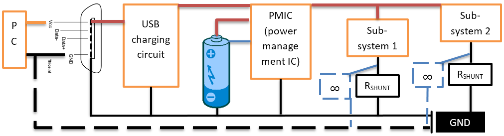
The focus of current measurement in a mobile system like a phone is when the system runs on battery.  Of course such a system should be charged regularly (from USB for all mobile devices I am concerned with), so such a system can be viewed like this:

Always remember that it's the PMIC that supplies current to the system, rather than the battery itself; a lithium-ion battery actually has thermistor output (the blue wire in the above diagram) and some charging circuit inside, which the PMIC actually looks for, so if you insert a plain AA battery, PMIC might not turn on the voltage to the rest of the system.

When measuring current, I cab insert a shunt resistor in one of the red or the black lines above, and measure the voltage drop across that resistor (ΔV = Vh - Vl), like this:
If Rshunt (shunt resistor) is inserted in the red line above, it is called the high side shunt resistor, and if placed on the black line, it is called the low side shunt resistor.  For the high side measurement case, Vh may stay roughly constant.  But according to the Ohm's law, Vl will change according to the current flow: the higher the current, the lower Vl will be, as shown below, where the cursors A1 and A2 mark a current spike event:
If Rshunt is relatively large, the system downstream of the Rshunt sees a noticeable voltage swing in the supply current.  Some components are relative intolerant of such voltage swing, and the system may not operate correctly.  Therefore, I have to keep Rshunt small (< 1 Ohm).  But since the current is tiny and Rshunt has to be a small, ΔV is small: typically << 10 mA.  An average hand-held multi-meter CANNOT measure such tiny voltage, but expensive multi-meter like this can.
Clamp-style current meters can measure current just with magnetic field induced by current flowing in a wire, so that I don't have to cut existing circuit and I don't have to worry about the ground isolation (see below).  BUT:
  1. In a tiny mobile system, it is difficult to put a huge clamp around tiny wires.
  2. The currents are on the order of uA and at most a few mA, and finding a reasonably priced yet sensitive clamp current meter that will work in this range is difficult.

Compelling need for ground isolation

Another reason that professional desktop multi-meters are expensive a lot of money for multi-meter is that the ground is isolated from the wall.  Let's modify the original block diagram with a shunt resistor and a multi-meter measuring across it (represented as an idealized infinite resistance below), and also connect the unit to a USB power source, such as a PC:
When I connect the multi-meter, the Vl junction of Rshunt is now connected to the multi-meter's negative terminal.  IF that negative terminal is grounded to the wall, then Vl is now tracking the wall ground--and that is OK so far, because the system GND (negative terminal of the battery) can just be lower potential than the wall ground (we are only talking about a few volts difference at most, so that we don't have to talk about ESD).  But if I connect another ground--such as the USB current source--to the GND, I have introduced a ground loop.  I's quite easy to forget this and damage the circuit.  Isolated negative terminal of the multi-meter protects against this sin.

Ground isolation is also necessary if I want to measure current across more than 1 shunt resistor.  Suppose I want to measure the digital and analog portion of the system separately, both on the high side.  Since the Vl for the digital and analog portions will be at different potentials, the negative terminals of the multi-meter connecting to the Vl_d and Vl_a MUST NOT be connected.  Unfortunately, most reasonable instruments share the negative terminal of ALL channels--to its power supply ground no less, so you cannot avoid the ground loop in that case.

Measuring on the lower side is only slightly better

To some extent, I can work around the ground loop problem by putting ALL Rshunt on the lower side, as illustrated below:
Measuring on the low side does NOT relieve us from the need to have a common ground across all negative terminals connected to the system; only proper ground isolated instruments can do that.  In the above picture, I am running the virtual scope on the same PC that is also charging the DUT over USB.  If I used 2 different PC--one connected to the USB port, and the other serving at the virtual scope for measuring the voltage across the shunt resistors, a ground loop will result.

Nov 15, 2015

Understanding the ADI ADV7511 DRM Linux driver

When I tried the Qt on Zedboard last time, I was overwhelmed by the complexity of the Linux graphics stack involving OpenGL.  I asked for any pointers to the Qt user forum, but didn't get any suggestion, so I just stuck with the Qt Widgets based program with the framebuffer backend. This time, I found this excellent explanation of the Linux graphics stack.

High level view of the Linux DRM SW stack

While reading this gem of a discourse, I found the Linux graphics stack images (this and this) on wiki to be indispensable for understanding the complex relationships between different moving parts.
Pearls of wisdom from Mr. Kitching's explanation:
An X server is a complicated thing; a recent count of source code lines showed the xorg X11 server to have significantly more lines of code than the Linux kernel.  ...In “direct rendering”, [sig] the server returns the ID of a local device node (/dev/dri/card*) which the client then opens (or in DRI3, an already-open file handle is returned). The client then uses libdrm to perform operations on this device-node in order to allocate graphics buffers and map them into the client’s memory-space. 
First were the “framebuffer” kernel drivers. These provide a fairly simple API that is capable of setting the graphics mode on the “main” output for a graphics chip, allowing applications to explicitly set individual pixels in the output framebuffer, and do a few simple accelerated operations (bitblits and rectangular fills). Framebuffer drivers expose a file /dev/fb{n} which userspace performs reads/writes and ioctls on; all card-specific drivers provide exactly the same API so userspace apps can use any framebuffer driver.  Modern cards ... often require drivers to generate GPU “programs” to do even 2D graphics - a far from trivial process. 
DRM drivers were created to support the DRI (direct rendering infrastructure): [user-space programs (like "window backing buffers", vertex graphs, textures, shader programs, and configuration commands)--through /dev/dri/* nodes--] allocate memory buffers, fill them with data or GPU instructions (through user-space library libdrm), and pass them to towards to GEM or TTM code, which passes the data/instruction to the graphics card.  The results are rendered into another buffer which is then submitted to the X server for composition.   DRI can theoretically be used to accelerate all sorts of graphics but in practice it is used for OpenGL.  The “DRM v2” drivers also support mode-setting (aka KMS). 
TTM kernel module provide a common kernel-private API for managing the transfer of data between system and GPU. Because TTM covered both the mem-on-card and UMA use cases, the API was quite complicated. The GEM (graphics execution manager) kernel module (really part of DRM; [provides a library of functions for managing memory buffers for GPUs]) was invented shortly after, with a much simpler API and a much simpler implementation - but it only supported UMA (it was developed by Intel who only produce integrated graphics). The TTM code was later reworked to keep the same functionality but provide the same simple API as GEM (“GEMified TTM”). 
EGL is an API for managing windows and buffers [-- and NOT for drawing operations; therefore EGL is merely a helper for OpenGL].  An OpenGL implementation is primarily responsible for generating appropriate blocks of data for a card to process, i.e. textures, tables of vertices, and streams of instructions - and all of this is card-specific but not operating system specific. However the data needs to be put into some buffer; OpenGL just requires the necessary buffers to be passed in as parameters, in order to retain its OS-independence. These buffers also need to be pushed to the card at some time. The responsibility of managing “windows” and “buffers” and “submitting” data has always been done external to OpenGL.  EGL was therefore invented as a standard API which can have a different implementation for each OS/windowing system. An app coded against the EGL and OpenGL interfaces therefore just needs to be linked to the right library at compile or runtime. 
The main use of DRI is to provide hardware acceleration for the Mesa implementation of OpenGL. DRI has also been adapted to provide OpenGL acceleration on a framebuffer console without a display server running.  DRI implementation is scattered through the X Server and its associated client libraries, Mesa 3D and the Direct Rendering Manager kernel subsystem.
In summary, modern graphics stack on Linux is vastly more complicated than the simple frame buffer used in early embedded systems.  It is challenging to understand a total system consisting of GPU HW (perhaps SW simulated), OpenGL API, and DMA operations between memory and GPU--because the code is scattered through the userspace, kernel, and even the HW (there is code to produce the HW, as well as the FW running on the remote HW itself).  But I hope to digest all of it--a bite at a time, starting with creation of the system to run Qt Quick OpenGL applications.

Creating a rootfs capable of running a QtQuick Control application

I don't have a GPU on the Zedboard that implements the OpenGL calls QtQuick will make, I will HAVE TO enable the mesa 3D (which is the open source implementation of OpenGL) in Buildroot, because Qt Quick requires OpenGL, as you can see in Qt Embedded document:
Some devices require vendor specific adaptation code for EGL and OpenGL ES 2.0 support. This is not relevant for non-accelerated platforms, for example the ones using the LinuxFB plugin, however neither OpenGL nor Qt Quick 2 will be functional in such a setup. 
The directory qtbase/mkspecs/devices contains configuration and graphics adaptation code for a number of devices. For example, linux-rasp-pi2-g++ contains build settings, such as the optimal compiler and linker flags, for the Raspberry Pi 2, and either an implementation of the eglfs hooks (vendor-specific adaptation code), or a reference to a suitable eglfs device integration plugin. The device is selected through the configure tool's -device parameter. The name that follows after this argument must, at least partially, match one of the subdirectories under devices.
To wit, in my Buildroot's Qt build folder, I only see the following "devices":

henry@w540:~/band/buildroot$ ls output/build/qt5base-5.5.0/mkspecs/devices/
common                           linux-buildroot-g++              linux-rasp-pi-g++
linux-archos-gen8-g++            linux-imx53qsb-g++               linux-sh4-stmicro-ST7108-g++
linux-arm-amlogic-8726M-g++      linux-imx6-g++                   linux-sh4-stmicro-ST7540-g++
linux-arm-hisilicon-hix5hd2-g++  linux-mipsel-broadcom-97425-g++  linux-snowball-g++
linux-arm-trident-pnx8473-g++    linux-odroid-xu3-g++             linux-tegra2-g++
linux-beagleboard-g++            linux-rasp-pi2-g++

Q: Does QtQuick require Mesa DRI?
A: Yes.  The following example shows that QtQuick app tries to load the DRI driver for the detected card, and then tries to fail back to swrast_dri driver.

QML_IMPORT_PATH: ./Qt5.2.0/gcc_64/qml:/home/james/src/ButtleOFX_Alpha_Linux64_v2.0/ButtleOFX/QuickMamba/quickmamba/../qml
"Qt Warning - invalid keysym: dead_actute" 
view <PyQt5.QtQml.QQmlEngine object at 0x7f63c3ce7640>
libGL error: unable to load driver: nouveau_dri.so
libGL error: driver pointer missing
libGL error: failed to load driver: nouveau
libGL error: unable to load driver: swrast_dri.so
libGL error: failed to load driver: swrast

To my dismay, I found that swrast DRI driver requires X11R7 in Buildroot (BR2_PACKAGE_XORG7)--but not the server.  So my Buildroot config contains the following packages:
  • Run a getty (login prompt) after boot
  • System configuration
    • Dynamic using devtmpfs + eudev <-- Qt5 eglfs_kms support seems to require it
    • supply root password <-- only to ssh into the target from the QtCreator using password
  • Target packages
    • Debugging
      • gdb <-- only to pick up gdbserver for debugging Qt application remotely
    • Graphics
      • mesa3d
        • DRI swrast driver: OpenGL implementation using the DRI infrastructure
        • OpenGL EGL: this is the API for managing windows and buffers
        • OpenGL ES: this is the OpenGL API
      • Qt5
        • Approve free license (Qt asks to approve the Qt free license during build)
        • gui module
          • OpenGL support
            • OpenGL API
              • OpenGL ES 2.0+
          • X.org XCB support
          • eglfs support (means egl full-screen): Qt Quick applications crash on startup without this, but why does Buildroot automatically select "linuxfb support" when I choose this?
          • GIF support
          • JPEG support
          • PNG support
        • qt5graphicaleffects
        • qt5quickcontrols
      • X.org X Window system
        • xorg-server (to avoid Qt Quick application saying "Could not open display")
          • Modular X.org (because KDrive/TinyX uses framebuffer instead of DRM)
        • X11 applicatoins
          • xinit: X window system initializer
    • Networking
      • openssh <-- this is ONLY to debug Qt application remotely
  • Libraries
    • Graphics
      • Q: what about libdri2 (DRI2 extension to the X window system)?
      • libdrm
        • Install test programs <-- for sanity testing DRM drivers
I changed buildroot/packages/qt5/qt5base/qt5base.mk to pick up support for KMS (and get rid of the unnecessary platforms):

QT5BASE_CONFIGURE_OPTS += \
-optimized-qmake \
-kms -no-xcb -no-directfb -no-linuxfb \
-no-cups \
-no-nis \
-no-iconv \
-system-zlib \
-system-pcre \
-no-pch \
-shared

Running 'make' at the buildroot top level starts the rootfs build process, which should take about half hour (much faster if rebuilding with ccache enabled) on an average modern laptop.

Allow root ssh into the target for remote debugging

When I tried to ssh into the target from the development laptop, the target's sshd refused connection.  I don't remember previous opensshd doing this before, but if you run into this, just add the following line into the rootfs's /etc/ssh/sshd_config:

PermitRootLogin yes

Now I could create a new "Generic Linux" device in QtCreator, and pass the test of connecting to the target.  It would be better to change the rootfs skeleton used by Buildroot, but I'll come back to this later.

Resulting rootfs

X (and not even the Xserver) adds nearly than 50 MB to the Linux rootfs size--in fact it is larger than all other parts of the linux rootfs COMBINED, as you can see below, where uImage is the uncompressed kernel image, and the rootfs.tar is the uncompressed image of the rootfs.

henry@w540:~/band/buildroot$ ls -lgh output/images/
total 205M
-rw-r--r-- 1 henry  69M Nov  1 08:35 rootfs.cpio
-rw-r--r-- 1 henry  31M Nov  1 08:35 rootfs.cpio.gz
-rw-r--r-- 1 henry  31M Nov  1 08:35 rootfs.cpio.uboot
-rw-r--r-- 1 henry  70M Nov  1 08:35 rootfs.tar
-rwxr-xr-x 1 henry 2.1M Oct 31 17:09 u-boot
-rw-r--r-- 1 henry 3.5M Oct 31 17:11 uImage
-rw-r--r-- 1 henry  11K Oct 31 17:11 zynq-zed-adv7511.dtb

ADI did not supply a DRI driver for the HDMI device--at least none that Buildroot knows about, so there is only swrast_dri:

# ls /usr/lib/dri/
swrast_dri.so

The "-kms" into the Qt base config shown in the previous section causes Qt to emit the eglfs-kms integration library:

# ls /usr/lib/qt/plugins/egldeviceintegrations/
libqeglfs-kms-integration.so  libqeglfs-x11-integration.so

Without this dynamic library, Qt eglfs will just fall back to the eglfs_x11, which I do NOT want to use (took too much code from just the X lib required for mesa eglfs and swrast).

Following the procedures I've used in the past (this and this), I network boot Linux on my Zedboard.  On boot, the target has used about 54 MB of RAM, according to /proc/meminfo:

# cat /proc/meminfo
MemTotal:         500148 kB
MemFree:          446284 kB
MemAvailable:     475100 kB
...

I chose -Os over space optimizing option, and I am sure the network stack eats up a large amount of RAM, but I will continue with the convenient network development environment for now.

During bootup, the axi-hdmi device driver is probed, as you can see from dmesg:

[drm] Initialized drm 1.1.0 20060810
platform 70e00000.axi_hdmi: Driver axi-hdmi requests probe deferral
...
axi-hdmi 70e00000.axi_hdmi: fb0:  frame buffer device
axi-hdmi 70e00000.axi_hdmi: registered panic notifier
[drm] Initialized axi_hdmi_drm 1.0.0 20120930 on minor 0

The probing is happens during platform driver init, because the axi_hdmi_tx driver is declared in the DTS.

Driver parameters are declared to the kernel in DTS

For an ARM Linux target to boot, 3 binaries are read (at minimum):

  1. Compressed Linux kernel image
  2. DTB (device tree blob) which is compiled from DTS
  3. Root file system--unless the target mounts a non-volatile file system.

The axi_hdmi_tx driver entry is found in zynq-zed-adv7511.dtsi:

axi_hdmi@70e00000 {
compatible = "adi,axi-hdmi-tx-1.00.a";
reg = <0x70e00000 0x10000>;
encoder-slave = <&adv7511>;
dmas = <&axi_vdma_0 0>;
dma-names = "video";
clocks = <&hdmi_clock>;
};

The DTS tells the driver the HW register address to read/write to.  It also identifies the DMA device driver: axi_vdma DTS node (although how it does this is unnecessarily complicated for the common case of just 1 DMA driver; dma-names establishes the array of DMA drivers can be used among the "dmas".  So the 1st element axi_vdma is named "video" in the DTS.  The driver later looks for the DMA driver "video" just named.  Despite the wild goose-chase, the driver finds the axi_vdma, which has the following DTS description:

axi_vdma_0: axivdma@43000000 {
compatible = "xlnx,axi-vdma";
#address-cells = <1>;
#size-cells = <1>;
#dma-cells = <1>;
#dma-channels = <1>;
reg = <0x43000000 0x1000>;
xlnx,include-sg = <0x0>;
xlnx,num-fstores = <0x3>;
dma-channel@43000000 {
compatible = "xlnx,axi-vdma-mm2s-channel";
interrupts = <0 59 0x4>;
xlnx,datawidth = <0x40>;
xlnx,genlock-mode = <0x0>;
xlnx,include-dre = <0x0>;
};
};

Even though this investigation is about the ADI ADV7511 DRM device driver, DMA is essential for high performance device driver.  So I will look into how the DRM driver uses DMA further down below.  Just like the adv7511 encoder driver, the vdma parameters are largely cryptic until you read the IP datasheet.  I studied the Xilinx VDMA IP when I worked on an image sensor bringup on Zynq, and remember that the datawidth is the number of bytes in each DMA transfer, num-fstores means the size of frame ring buffer.   Note that the DMA controller exposes its own register at another address that was decided in the HW design.  So let's take a detour through the HW land to better understand the memory mapping before diving into the device driver.

The HW controlled by the DRM driver

The HW registers base address is seen above matches the Vivado HW configuration as shown below.
The axi_hdmi_core is Verilog code from ADI, shown in the upper right corner (where both the yellow control signals and the green data signals are going to) of the Zynq HW design diagram below.

It is this axi_hdmi_tx IP that shakes the HDMI pins routed to the ADV7511 sitting a couple of inches away from the Zynq processor on the Zedboard.  To find the trace for these pins (shown to the right of the axi_hdmi_tx IP in the above schematic), one can consult the Vivado constraint file:

set_property  -dict {PACKAGE_PIN  W18   IOSTANDARD LVCMOS33} [get_ports hdmi_out_clk]
set_property  -dict {PACKAGE_PIN  W17   IOSTANDARD LVCMOS33} [get_ports hdmi_vsync]
set_property  -dict {PACKAGE_PIN  V17   IOSTANDARD LVCMOS33} [get_ports hdmi_hsync]
set_property  -dict {PACKAGE_PIN  U16   IOSTANDARD LVCMOS33} [get_ports hdmi_data_e]
set_property  -dict {PACKAGE_PIN  Y13   IOSTANDARD LVCMOS33} [get_ports hdmi_data[0]]
...
set_property  -dict {PACKAGE_PIN  V13   IOSTANDARD LVCMOS33} [get_ports hdmi_data[15]]

Note that the axi_hdmi_tx IP does NOT control the I2C pins--which is how one reads/writes the ADV7511 registers.  That is done through the axi_iic_main IP (the one right below the axi_hdmi_dma IP in the above schematic), through the S_AXI bus--as I learned more than a year ago, when first bringing up my Zedboard HDMI display.  In the memory map screenshot above, the base address of the axi_iic_main was assigned 0x4160_0000.  In summary, we now know that there are  at least 3 HW to control for the ADV7511 video operation:
  1. Low bandwidth ADV7511 internal register read/write through I2C: mediated by the Xilinx axi_iic_main IP
  2. High bandwidth parallel bus pixel data transmission to the ADV7511: mediated by the axi_hdmi_tx IP
  3.  DMA frame buffer from the system memory to axi_hdmi_tx IP: axi_hdmi_dma IP
In all cases (including sending the I2C packets), the Linux kernel interfaces with the HW through memory mapped registers.  Let's now change direction and approach the problem from the userspace application side.

Application that uses the DRM driver: QtQuick clocks demo on Zedboard

To create any Qt project in QtCreator, you need a "kit" (Tools --> Options --> Build & Run --> Kits tab), so I created "Zed" kit, as shown below:
Tip: fix any errors flagged by the QtCreator in this window. 

QtCreator comes with many examples, and Qt team's energy is going to the Qt Quick, so I chose the Clocks demo from the choices.

When creating a project in QtCreator, you have to choose the kits for the project.  I must not forget the "Zed" kit I just created above before clicking "Configure project".

Controlling a Qt eglfs_kms "platform" behavior

Supported command line arguments for any Qt eglfs app:
  • -platformpluginpath
  • -platform
  • -platformtheme
  • -qwindowgeometry
  • -qwindowtitle
  • -qwindowicon
Qt eglfs supports the following environment variable:
  • QT_QPA_EGLFS_INTEGRATION: eglfs_ms
  • QT_QPA_EGLFS_DEBUG: 1
  • QT_QPA_EGLFS_CURSOR: ??
  • QT_QPA_EGLFS_KMS_CONFIG
And just to ensure that X is out of the picture, I unset the DISPLAY environment (":0.0" by default) in the QtCreator's project run configuration window (Projects --> Build & Run --> <your kit> --> Run), as you can see below:

Supposedly, the KMS/DRM backend also supports custom configurations via a JSON file. Set the environment variable QT_QPA_EGLFS_KMS_CONFIG to the name of the file to enable this. The file can also be embedded in the application via the Qt resource system. An example configuration (TODO: try this out):

  {
    "device": "/dev/dri/card1",
    "hwcursor": false,
    "pbuffers": true,
    "outputs": [
      {
        "name": "VGA1",
        "mode": "off"
      },
      {
        "name": "HDMI1",
        "mode": "1024x768"
      }
    ]
  }

When I hit the debug key (F5), launching the project on the target worked, and I see the 7 clocks (New York, London, etc.).  The clocks definitely do not keep up, even though the CPU is pegged.  Whittling down the clock list to just 1 is still not enough to make the clock rendering real-time.  Perhaps because the renering is falling behind, I get the following error messages:

QEGLPlatformContext: Failed to make temporary surface current, format not updated
Could not set cursor: -6
Failed to move cursor: -14
Could not queue DRM page flip! (Invalid argument)
...

The initial "temporary surface current" failure is happens at the very first render as the OpenGL context is created, in qeglplatformcontext.cpp, as you can see in this stack trace:

0 QEGLPlatformContext::updateFormatFromGL qeglplatformcontext.cpp 327 0xb5890d38
1 QOpenGLContext::create qopenglcontext.cpp 597 0xb68cbab8
2 QSGThreadedRenderLoop::handleExposure qsgthreadedrenderloop.cpp 912 0xb6dca064
3 QSGThreadedRenderLoop::exposureChanged qsgthreadedrenderloop.cpp 854 0xb6dca4f0
4 QQuickWindow::exposeEvent qquickwindow.cpp 207 0xb6df4a98
5 QWindow::event qwindow.cpp 2028 0xb68944e8
6 QQuickWindow::event qquickwindow.cpp 1414 0xb6e01afc
7 QCoreApplicationPrivate::notify_helper qcoreapplication.cpp 1093 0xb5f9f1d0
8 QCoreApplication::notify qcoreapplication.cpp 1038 0xb5f9f254
9 QCoreApplication::notifyInternal qcoreapplication.cpp 965 0xb5f9eedc
10 sendSpontaneousEvent qcoreapplication.h 227 0xb688b78c
11 QGuiApplicationPrivate::processExposeEvent qguiapplication.cpp 2643 0xb688b78c
12 QGuiApplicationPrivate::processWindowSystemEvent qguiapplication.cpp 1644 0xb688c850
13 QWindowSystemInterface::sendWindowSystemEvents qwindowsysteminterface.cpp 608 0xb686ee48
14 QWindowSystemInterface::flushWindowSystemEvents qwindowsysteminterface.cpp 592 0xb68713c0
15 QEglFSWindow::setVisible qeglfswindow.cpp 185 0xb5887780
16 QWindow::setVisible qwindow.cpp 516 0xb6892940
17 QWindow::showFullScreen qwindow.cpp 1832 0xb6893554
18 main main.cpp 41 0x94a4

I don't know how serious the warning ("Failed to make temporary surface current") is, but this helped me set a break-point in the render path, which of course must happen before the ADV7511 can render on the screen.  This stack trace indirectly demonstrates the difficulty of understanding/debugging modern multi-threaded applications: threads loosely cooperate through events--such as the "expose" event in this example.  When I step through the debugger, it appears that no slots are connected to this signal YET.  The QOpenGLContext (along with QQuickAnimatorController and QSGRenderContext) just created is "moved" to the QSGRenderThread (Qt Quick scene graph render thread)--that is, the OpenGL context is now owned by the Qt Quick scene graph render thread--which is started in this path.  The QSGRenderThread loops in the following loop while active:

  1. if window: syncAndRender()
  2. processEvents()
  3. if not pendingUpdate or not window: processEventsAndWaitForMore()

The last "wait" is what prevents the render thread from spinning.  So at a high level, the QSG render thread will syncAndRender() when an update is pending.  I dug out the following brief description of the OpenGL context usage from the QOpenGLContext class introduction:
A context can be made current against a given surface by calling makeCurrent(). When OpenGL rendering is done, call swapBuffers() to swap the front and back buffers of the surface, so that the newly rendered content becomes visible. To be able to support certain platforms, QOpenGLContext requires that you call makeCurrent() again before starting rendering a new frame, after calling swapBuffers().
During sync, a window is rendered recursively, as you can see in the stack trace:

0 vbo_validated_drawrangeelements vbo_exec_array.c 947 0xb541761c
1 vbo_exec_DrawElements vbo_exec_array.c 1128 0xb541761c
2 glDrawElements glapi_mapi_tmp.h 1635 0xb5d071ac
3 glDrawElements qopenglfunctions.h 724 0xb6d72878
4 QSGBatchRenderer::Renderer::renderMergedBatch qsgbatchrenderer.cpp 2296 0xb6d72878
5 QSGBatchRenderer::Renderer::renderBatches qsgbatchrenderer.cpp 2486 0xb6d7309c
6 QSGBatchRenderer::Renderer::render qsgbatchrenderer.cpp 2674 0xb6d798c0
7 QSGRenderer::renderScene qsgrenderer.cpp 208 0xb6d86d3c
8 QSGRenderer::renderScene qsgrenderer.cpp 168 0xb6d87524
9 QSGRenderContext::renderNextFrame qsgcontext.cpp 558 0xb6d9c104
10 QQuickWindowPrivate::renderSceneGraph qquickwindow.cpp 383 0xb6df7e80
11 QSGRenderThread::syncAndRender qsgthreadedrenderloop.cpp 593 0xb6dc3f0c
...

In my case, I am using the SW renderer but glDrawElements() very is near where the rubber meets the road (GPU).  During the leaf item render, rendering operations (translate, scale, rotate, clip) is performed on the item, and the QSGBatchRenderer handles the opaque and alpha items appropriately in SW, as you can see below:

        if (m_opaqueBatches.size())
            std::sort(&m_opaqueBatches.first(), &m_opaqueBatches.last() + 1, qsg_sort_batch_decreasing_order);

        // Sort alpha batches back to front so that they render correctly.
        if (m_alphaBatches.size())
            std::sort(&m_alphaBatches.first(), &m_alphaBatches.last() + 1, qsg_sort_batch_increasing_order);

I don't know why the cursor is treated differently than any other item, but it is the last item to be painted before swap buffer.

    if (surface->surface()->surfaceClass() == QSurface::Window) {
        QPlatformWindow *window = static_cast<QPlatformWindow *>(surface);
        if (QEGLPlatformCursor *cursor = qobject_cast<QEGLPlatformCursor *>(window->screen()->cursor()))
            cursor->paintOnScreen();
    }

    qt_egl_device_integration()->waitForVSync(surface);
    QEGLPlatformContext::swapBuffers(surface);
    qt_egl_device_integration()->presentBuffer(surface);

The cursor is treated specially because a HW may have a dedicated "plane" for cursor (vs. what is under the cursor).  It even gets its own ioctl number: DRM_IOCTL_MODE_CURSOR (0xC01C64A3), which fails with error code -6 (ENXIO).  I will do justice to the axi_hdmi_tx driver in the next section, but for the impatient. the DRM ioctls are defined in the <kernel>/include/uapi/drm/drm.h and implemented in <kernel>/dgpu/drivers/drm/drm_ioctl.c, as shown in the following code snippet:

static const struct drm_ioctl_desc drm_ioctls[] = {
...
DRM_IOCTL_DEF(DRM_IOCTL_MODE_SETCRTC, drm_mode_setcrtc, DRM_MASTER|DRM_CONTROL_ALLOW|DRM_UNLOCKED),
DRM_IOCTL_DEF(DRM_IOCTL_MODE_GETPLANE, drm_mode_getplane, DRM_CONTROL_ALLOW|DRM_UNLOCKED),
DRM_IOCTL_DEF(DRM_IOCTL_MODE_SETPLANE, drm_mode_setplane, DRM_MASTER|DRM_CONTROL_ALLOW|DRM_UNLOCKED),
DRM_IOCTL_DEF(DRM_IOCTL_MODE_CURSOR, drm_mode_cursor_ioctl, DRM_MASTER|DRM_CONTROL_ALLOW|DRM_UNLOCKED),
...

The 2nd argument into the DRM_IOCTL_DEF is the function that implements the ioctl.  So I checked drm_mode_cursor_ioctl(), which called drm_mode_cursor_common(), which revealed why ENXIO was returned: the driver (<>/drivers/gpu/drm/adi_axi_hdmi) does NOT have a separate cursor plane, and it does NOT provide the cursor related functions, as you can see in axi_hdmi_crtc.c:

static struct drm_crtc_helper_funcs axi_hdmi_crtc_helper_funcs = {
 .dpms = axi_hdmi_crtc_dpms,
 .prepare = axi_hdmi_crtc_prepare,
 .commit = axi_hdmi_crtc_commit,
 .mode_fixup = axi_hdmi_crtc_mode_fixup,
 .mode_set = axi_hdmi_crtc_mode_set,
 .mode_set_base = axi_hdmi_crtc_mode_set_base,
 .load_lut = axi_hdmi_crtc_load_lut,
};

Since I do NOT want to show the cursor anyway, I ignore the cursor related warning messages and move on.  During the front and back buffer swap, the rendered image is blitted to the back buffer.  In the SW rasterization (my case), the entire screen worth of pixel * 4 bytes/pixel are memcpy'ed as you can see in the following snipptet in the mesa's platform_drm.c:

   for (i = 0; i < height; i++) {
      memcpy(bo->map + (x + i) * internal_stride + y,
             data + i * stride, stride);
   }

After the frame buffer to be shown is finally ready, ioctl(DRM_IOCTL_MODE_SETCRTC) is finally called from QEglFSKmsScreen::flip():

    if (!m_output.mode_set) {
        int ret = drmModeSetCrtc(m_device->fd(),
                                 m_output.crtc_id,
                                 fb->fb,
                                 0, 0,
                                 &m_output.connector_id, 1,
                                 &m_output.modes[m_output.mode]);

        if (ret)
            qErrnoWarning("Could not set DRM mode!");
        else
            m_output.mode_set = true;
    }

    int ret = drmModePageFlip(m_device->fd(),
                              m_output.crtc_id,
                              fb->fb,
                              DRM_MODE_PAGE_FLIP_EVENT,
                              this);
    if (ret) {
        qErrnoWarning("Could not queue DRM page flip!");
        gbm_surface_release_buffer(m_gbm_surface, m_gbm_bo_next);
        m_gbm_bo_next = Q_NULLPTR;

    }

As seen in the QtCreator debug view, the rendering seems to be triggered by DRM_IOCTL_MODE_SETCRTC.  Now that we have identified at least 1 DRM ioctl that seems to work, let's dive into the driver.

axi_hdmi_tx DRM driver in action

The best tool I've found so far to understand the kernel and (statically linked) driver code is with a JTAG debugger.  Following the procedure in this blog entry, I start setting hardware breakpoints in the driver.  The following is what I've been able to surmise this way--and by browsing the driver code.

According to the ADI's axi_hdmi_tx device driver "documentation" (if you call a 1 pager a documentation), "the driver [axi_hdmi_drm] is implemented as a DRM KMS driver"--which means very little to anyone except the few people in the world who actually write DRM device drivers.  But this picture on the Xilinx DRM KMS driver wiki helps.
The ADV7511 is an HDMI transmitter, and not a GPU, so the ADI's ADV7511 driver is at most the encoder and connector in the above block diagram.  As seen in the DTS entry in the previous section, the axi_hdmi_tx DRM driver (<kernel>/drivers/gpu/drm/adi_axi-hdmi/axi_hdmi_drv.c) is the master of the adv7511 encoder driver hanging off the axi-iic device driver (its sibling is the adau1761 device driver), with the following DTS property:

adv7511: adv7511@39 {
compatible = "adi,adv7511";
reg = <0x39>;

adi,input-style = <0x02>;
adi,input-id = <0x01>;
adi,input-color-depth = <0x3>;
adi,sync-pulse = <0x03>;
adi,bit-justification = <0x01>;
adi,up-conversion = <0x00>;
adi,timing-generation-sequence = <0x00>;
adi,vsync-polarity = <0x02>;
adi,hsync-polarity = <0x02>;
adi,tdms-clock-inversion;
adi,clock-delay = <0x03>;
};

These ADI properties remain largely a mystery even when matched against the counterparts in <kernel>/drivers/gpu/i2c/adv7511.h, as in the code snippet below:

/**
 * enum adv7511_input_bit_justifiction - Selects the input format bit justifiction
 * ADV7511_INPUT_BIT_JUSTIFICATION_EVENLY: Input bits are evenly distributed
 * ADV7511_INPUT_BIT_JUSTIFICATION_RIGHT: Input bit signals have right justification
 * ADV7511_INPUT_BIT_JUSTIFICATION_LEFT: Input bit signals have left justification
 **/
enum adv7511_input_bit_justifiction {
ADV7511_INPUT_BIT_JUSTIFICATION_EVENLY = 0,
ADV7511_INPUT_BIT_JUSTIFICATION_RIGHT = 1,
ADV7511_INPUT_BIT_JUSTIFICATION_LEFT = 2,
};

/**
 * enum adv7511_input_color_depth - Selects the input format color depth
 * @ADV7511_INPUT_COLOR_DEPTH_8BIT: Input format color depth is 8 bits per channel
 * @ADV7511_INPUT_COLOR_DEPTH_10BIT: Input format color dpeth is 10 bits per channel
 * @ADV7511_INPUT_COLOR_DEPTH_12BIT: Input format color depth is 12 bits per channel
 **/
enum adv7511_input_color_depth {
ADV7511_INPUT_COLOR_DEPTH_8BIT = 3,
ADV7511_INPUT_COLOR_DEPTH_10BIT = 1,
ADV7511_INPUT_COLOR_DEPTH_12BIT = 2,
};

When the curiosity gets strong enough, I download the chip datasheet and start reading.  But since this is a very complex chip (its footprint is almost as large as the Zynq processor itself!), sufficient understanding my not be possible without actually bringing it up myself.  For the purpose of understanding the Linux display stack, I think just following the currently working code path is sufficient.  Many of the parameters in the DTS will eventually be written to the ADV7511 over I2C through the regmap API, as in this example in adv7511_set_link_config():

regmap_update_bits(adv7511->regmap, ADV7511_REG_VIDEO_INPUT_CFG1, 0x7e,
  (config->input_color_depth << 4) |
  (config->input_style << 2));

There are combined 70 such references to adv7511->regmap in adv7511_audio.c and adv7511_core.c.  This regmap is an instance of the i2c regmap.  Take a look at the Linux's rich support for the all different ways to interface to an external IC:

henry@w540:~/band/adi_kernel/drivers/base/regmap$ ls *.c
regcache.c       regcache-rbtree.c  regmap-debugfs.c  regmap-mmio.c
regcache-flat.c  regmap-ac97.c      regmap-i2c.c      regmap-spi.c
regcache-lzo.c   regmap.c           regmap-irq.c      regmap-spmi.c

Scanning the functions that use this regmap is a quick and dirty way to glean where the driver is interacting with the ADV7511 chip over I2C:

  • adv7511_set_colormap
  • adv7511_set_config
  • adv7511_set_link_cconfig
  • adv7511_packet_enable/disable
  • adv7511_hpd
  • adv7511_is_interrupt_pending
  • adv7511_get_edid_block (EDID: extended display identification data)
  • adv7511_get_modes (drm_mode.h defines DPMS flags that are bit compatible with Xorg definition: ON, STANDBY, SUSPEND, OFF)
  • adv7511_encoder_dpms
  • adv7511_encoder_detect
  • adv7511_encoder_mode_set
  • adv7511_probe

As mentioned in the lead-up to the HW overview, the "video" axi-vdma driver is a slave of the axi_hdmi_tx driver.  During the probe, a handle to that vdma driver is obtained with this code:

private->dma = dma_request_slave_channel(&pdev->dev, "video");

The master driver (axi_hdmi_tx) does not use this DMA directly, but delegates the DMA handle to the CRTC (see the vaguely explained device driver block diagram from ADI) in axi_hdmi_load() --> axi_hdmi_crtc_create(), which uses it in crtc_prepare() and crtc_update().  prepare() just terminates the current DMA, so all the interesting action is in update(), which is called from some of the crtc methods listed when discussing the (lack of) cursor support in this device driver:

  • crtc_commit()
  • crtc_dpms()
  • crtc_mode_set_base()

Apparently, the Xilinx VDMA needs a few config parameters before it can actually start work.  So the driver commands the VDMA IP twice to commence DMA transfer from memory to the axi_hdmi_tx IP.  The "error-free" code path is:

obj = drm_fb_cma_get_gem_obj(fb, 0);

axi_hdmi_crtc->dma_config.hsize = mode->hdisplay * fb->bits_per_pixel / 8;
axi_hdmi_crtc->dma_config.vsize = mode->vdisplay;
axi_hdmi_crtc->dma_config.stride = fb->pitches[0];

dmaengine_device_control(axi_hdmi_crtc->dma, DMA_SLAVE_CONFIG,
(unsigned long)&axi_hdmi_crtc->dma_config);

offset = crtc->x * fb->bits_per_pixel / 8 + crtc->y * fb->pitches[0];

desc = dmaengine_prep_slave_single(axi_hdmi_crtc->dma,
obj->paddr + offset,
mode->vdisplay * fb->pitches[0],
DMA_MEM_TO_DEV, 0);

dmaengine_submit(desc);
dma_async_issue_pending(axi_hdmi_crtc->dma);

Note the extensive use of existing kernel support for DMA.

This DRM driver does not support page flip

The repeated page flip error seems to be caused by the device driver (axi_hdmi_drm) ioctl(DRM_IOCTL_MODE_PAGE_FLIP = 0xC01864B0, flags = DRM_MODE_PAGE_FLIP_EVENT) failing with return code -22.
 (EINVAL) during OpenGL context swap buffer.  The only documentation I found so far on page flip is in the <kernel>/include/uapi/drm/drm_mode.h:
 * This ioctl will ask KMS to schedule a page flip for the specified
 * crtc.  Once any pending rendering targeting the specified fb (as of
 * ioctl time) has completed, the crtc will be reprogrammed to display
 * that fb after the next vertical refresh.  The ioctl returns
 * immediately, but subsequent rendering to the current fb will block
 * in the execbuffer ioctl until the page flip happens.  If a page
 * flip is already pending as the ioctl is called, EBUSY will be
 * returned.
 *
 * Flag DRM_MODE_PAGE_FLIP_EVENT requests that drm sends back a vblank
 * event (see drm.h: struct drm_event_vblank) when the page flip is
 * done.  The user_data field passed in with this ioctl will be
 * returned as the user_data field in the vblank event struct.
 *
 * Flag DRM_MODE_PAGE_FLIP_ASYNC requests that the flip happen
 * 'as soon as possible', meaning that it not delay waiting for vblank.
 * This may cause tearing on the screen.
The kernel drm wrapper code is set to return -EINVAL if the driver does NOT supply page_flip() method--as is the case here.  So perhaps one can live with this, and find a way to tell Qt eglfs_kms platform to NOT request page flip.

Accessing the DRM driver from userspace

The drm driver exposes a DRI interface file through the DRM infrastructure (somehow), as you can see below:
When loaded, a card-specific drm helper module calls into the drm module to register itself as a “drm driver”, and provides a set of function-pointers that the drm core module may invoke. The “drm core” then creates a file /dev/dri/card{n} on which IOCTLs can be made to talk to the driver.  [Through this file, “event” such as “vblank” or “flip complete” can be read.]  ...DRIVER_MODESET indicates that it supports kernel modesetting (KMS).
 userspace code can perform mode-setting (but not generate graphics) through the controlD{n} file.
The driver declares the supported features like this:

static struct drm_driver axi_hdmi_driver = {
.driver_features = DRIVER_MODESET | DRIVER_GEM,

If the flag includes DRIVER_RENDER, /dev/dri/renderD64 would have been created (<>/drivers/gpu/drm/drm_drv.c).

Conclusion

Without a GPU, the axi_hdmi driver could not render 1920x1080 pixels (~2M pixel) even at 1 Hz, to show the second hand moving; the SW rasterization took too much time.  This hints at the crushing amount of floating point calculations necessary for a modern 3D rendered GUI, because the same HW and driver had no problem refreshing a 2D GUI with Qt widgets API in previous projects.  It appeared that the CPU could update at roughly 1/3 Hz rate.  If I use a smaller screen (say 128x96 ~ 12K pixels), I should be able to update the screen at nearly 60 Hz using exactly the same HW and drivers MINUS the ADV7511 specific portion.  Of course, I will wind up pegging the CPU all the time, which is a huge point against SW rasterization.