For most of my career, I've worked only on super expensive products; frankly I am tired of it. Recently, I switched the industry and learned a lot about wireless/wearable consumer electronics at Jawbone. I've been looking for a cheap USB-capable (phone to the uC) uC for a recently started
hobby project, and decided to try the STM32L0 or STM32F0 line. STM32L052xx have 64/32 KB flash and 8 KB SRAM, and available in 32-pin QFN package. But STM32F042xx is even smaller, at 32/16 KB flash, 6 KB SRAM, and down to 20-pin (TSSOP) package. I bought both the nucleo-l053r8 eval board and the nucleo-f042k6 eval board--rounding out my STM32 eval board collection (I now have an eval board for the STM32 L0, L1, L4, F0, F4, and F7 lines. See my previous entries on
running Linux on the STM32F4, and running the
UBoot on STM32F7).
Update: after nearly 2 years of sitting on the problem, I found out why the device was not enumerating: it
does enumerate if you run the release code (vs. debug). But I still don't know the root cause.
Blinking the nucleo-32 user LED
Where ultra-low power consumption is not an overriding criteria, the F0 line is the more consumer/toy friendly option, so I begin my experiments with the nucleo-f042 board.
The big 3-color LED package right next to the micro-USB connector (at the top of the above picture) is the ST-Link indicator and is not accessible from the uC. Of the 2 LEDs on the bottom of the above picture, the green LED (on the right) is the LD3 that the uC can control on the PB3 pin (pin D12 on the nucleo32 board), as you can see in the hardware block diagram.
To blink this LED from my GNU ARM Eclipse CDT environment (I could use the Keil uVision since the flash is only 32 KB--the max size supported by the free license of the Keil uVision--but I am more familiar with the Eclipse CDT environment), I created a new C project using the GNUARMEclipse plugin's STM32F0xx C/C++ project template, as shown below.
In the next screen, I chose the STM32F042 chip family, and the correct flash and RAM size (32 and 6, respectively). The clock nominally an external clock source speed, but in this case it confusing, since this board does NOT have an external OSC, as you can see in the above block diagram. Since I plan to use the 8 MHz internal (on-chip) RC clock source (multiplied 6x to 48 MHz) as you can see below, I entered 8000000 for the "Clock (Hz)" textbox.
Of the remaining options, I whack the "Use newlib nano", to make the most of the code space.
To debug the project from Eclipse through OpenOCD (you have to download/compile OpenOCD itself, since the Eclipse OpenOCD plugin does not seem to come with the executable itself), a few setups are required. The Eclipse wide setup is available in Preferences --> Run/Debug --> OpenOCD. Currently, it consists of just the executable name and path. The debug configuration option for the project also needs to be told which OpenOCD config file to use for the board, as shown below.
After all this, the "blink" project does not blink at first, because the pin assignment is incorrect for the board. In the auto-generated BlinkLed.h, I changed the port and pin to PB3, as you can see below.
// Port numbers: 0=A, 1=B, 2=C, 3=D, 4=E, 5=F, 6=G, ...
#define BLINK_PORT_NUMBER (1)
#define BLINK_PIN_NUMBER (3)
With the green LED now blinking away, I proceed convert this FW into a USB HID device.
Generating USB HID FW code in STM32CubeMx
The CubeMX GUI can assign pin functions and generate code stub for USB. To get going, I just need to enable the USB FS 2.0 in the Pinout explorer. I also want to test USB remote wakeup from a button, so I assigned PA0 to EXTI0, as you can see in the pinout view:
During development, a testpoint I can watch on the scope is super-helpful, so I assigned PA1 to GPIO output. And I think the SWD semi-hosting is too slow, so I instead use UART2 to drive out SW tracing messages. At 8 sample/bit oversampling, I can drive out 6 Mbaud from this peripheral, but my FT232R USB to serial translator chip can only go up to 3 Mbit/s anyway, so I constrain the peripheral to 3 Mbps, as shown below.
If you want to transmit an uint8_t type as a trace, you have to increase the word length to 8 bits (not counting parity). If using the nucleo boards, the ST-Link VCOM port, using its VCOM port which shows up to the development Windows PC as a COMx device is a cleaner alternative--although I am not sure what maximum baud rate it supports.
I then generate a code through menu --> Project --> Generate code. I have to copy (and replace if necessary; you can actually just create softlinks) some of these files to the blinky project I just ran in the last section, by dragging and dropping the items into the Eclipse project explorer.
- Inc/* --> include/
- Src/* --> src/. Delete the existing Timer.c and Blink.c, since we will not be blinking the LED any more.
- Drivers/STM32F0xx_HAL_Driver/Inc/* (including the Legacy/ folder) --> system/include/stm32f0-stdperiph/. Note that the HAL headers have "_hal_" in the name.
- Drivers/STM32F0xx_HAL_Driver/Src/* --> system/src/stm32f0-stdperiph/. Delete the existing source files (those without "_hal_" in the name) since they are unnecessary now.
- Drivers/CMSIS/Device/ST/STM32F0xx/Include/*.h --> system/include/cmsis/
- Drivers\CMSIS\Device\ST\STM32F0xx\Source\Templates\system_stm32f0xx.c --> system/src/cmsis/
- Drivers\CMSIS\Device\ST\STM32F0xx\Source\Templates\gcc\startup_stm32f042x6.s --> system/src/cmsis/startup_stm32f042x6.S. The extension change from ".s" to ".S" is required because Eclipse CDT expects assembly file extension to be ".S".
- Middlewares/ST/STM32_USB_Device_Library/Core/Inc/* --> include/
- Middlewares/ST/STM32_USB_Device_Library/Core/Src/* --> src/
- Middlewares/ST/STM32_USB_Device_Library/Class/CustomHID/Inc/* --> include/
- Middlewares/ST/STM32_USB_Device_Library/Class/CustomHID/Src/* --> src/
The USB middleware files are necessary only because I want to use the ST's USB middleware. Initially, I tried to copy the folder Middlewares/ST/STM32_USB_Device_Library/ to the project root, but the GNUARMeclipse project template would not generate a recursive build rule for the STM32_USB_Device_Library folder I copied. Figuring I will switch to a Makefile in the end, I just worked around by copying the sources individually to existing include/ and src/ folders.
The CPP requires the chip definition, so I added a new symbol "STM32F042x6" to project properties --> C/C++ Build --> Settings --> Cross ARM C Compiler --> Preprocessor to ALL build configurations (Debug and Release). With this change, the project builds again, and I can run the FW from the debugger. But since I did not solder on USB connections, nothing interesting happens. Soldering on a USB connector itself is easy enough; the most time consuming part are figuring out the D+/D- pins (3 and 2, which are in the middle of the USB standard type A connector; pin 1 is the Vbus, on the right hand side of the connector when you look straight at the cable) and shielding the D+/D- cables, for anything but the low speed USB devices.

I connected the D- cable to PA11 (nucleo board CN3.14) and the D+ cable to PA12 (CN3.5). The Vbus cable is left unconnected until I will need to power the prototype from the Vbus. Now I should be able to connect this FW to a host PC, but before I dive into the USB HID, let me insert SW tracing library into the project--because I expect things to NOT work the first time.
Marrying QPN with the STM32 HAL
The 32 KB flash and 6 KB SRAM leaves no room for high level SW such as an OS or a standard lib. QPN is ideal for a moderately complex "multi-tasking" FW. QPN has already been ported to CM0+ (on nucleo-l053r8), so let's start with a working example: $(QPN)/examples/arm-cm/dpp_nucleo-l053r8. The example links against the nucleo-l053r8 board support files (I guess originally copied from the ST peripheral lib), but I am now generating all necessary files from the CubeMX, so I will just pick up the chip/board support from there.
I could not get CubeMX to change the code output folder (seems to be a bug), so I am living with the default output folder set when I created the CubeMX project. I am going to build the project with a slightly modified version of the QPN DPP example Makefile. The source and include paths should mirror the folders from which I copied manually in the first section above.
DRIVE := D:
QPN := $(DRIVE)/QP/qpn
# QP port used in this project
QP_PORT_DIR := $(QPN)/ports/arm-cm/qv/gnu
# I use CubeMX to generate the HAL and middleware files
CUBEMX_OUT := $(DRIVE)/uC/ST/play/nucleo-l042-hid
DEVICE := STM32F042x6
DEVICE_FAMILY := STM32F0xx
#Could not get this to work: DEVICE_FAMILY = $($(DEVICE):x%=xx)
HAL := $(CUBEMX_OUT)/Drivers/$(DEVICE_FAMILY)_HAL_Driver
CMSIS := $(CUBEMX_OUT)/Drivers/CMSIS
# list of all source directories used by this project
VPATH = $(QPN)/source $(QP_PORT_DIR) \
$(CUBEMX_OUT)/Src $(HAL)/Src \
$(CMSIS)/Device/ST/$(DEVICE_FAMILY)/Source/Templates \
$(CUBEMX_OUT)/Middlewares/ST/STM32_USB_Device_Library/Core/Src \
$(CUBEMX_OUT)/Middlewares/ST/STM32_USB_Device_Library/Class/CustomHID/Src
# list of all include directories needed by this project
INCLUDES = -I. \
-I$(QPN)/include -I$(QPN)/source -I$(QP_PORT_DIR) \
-I$(CUBEMX_OUT)/Inc -I$(HAL)/Inc \
-I$(CMSIS)/Include -I$(CMSIS)/Device/ST/$(DEVICE_FAMILY)/Include \
-I$(CUBEMX_OUT)/Middlewares/ST/STM32_USB_Device_Library/Core/Inc \
-I$(CUBEMX_OUT)/Middlewares/ST/STM32_USB_Device_Library/Class/CustomHID/Inc
C_SRCS := startup_stm32f042x6.c system_stm32f0xx.c \
bsp.c main.c philo.c table.c \
cubemx_main.c stm32f0xx_it.c usbd_conf.c usbd_desc.c \
usbd_core.c usbd_ctlreq.c usbd_ioreq.c \
stm32f0xx_hal_msp.c usb_device.c usbd_custom_hid_if.c \
usbd_customhid.c \
stm32f0xx_hal.c stm32f0xx_hal_pcd.c stm32f0xx_hal_rtc.c \
stm32f0xx_hal_cortex.c stm32f0xx_hal_pcd_ex.c stm32f0xx_hal_rtc_ex.c \
stm32f0xx_hal_dma.c stm32f0xx_hal_pwr.c stm32f0xx_hal_tim.c \
stm32f0xx_hal_flash.c stm32f0xx_hal_pwr_ex.c stm32f0xx_hal_tim_ex.c \
stm32f0xx_hal_flash_ex.c stm32f0xx_hal_rcc.c stm32f0xx_hal_uart.c \
stm32f0xx_hal_gpio.c stm32f0xx_hal_rcc_ex.c stm32f0xx_hal_uart_ex.c
QPN normally wants full control of the uC--running its tick update in the Systick_Handler, and handling the button press by directly checking the GPIO register. But since I am trying to assess the benefit of the STM32 HAL, I changed the QPN bsp.c to use the HAL.
void HAL_SYSTICK_Callback(void) //HAL will call me back from Systick_Handler
{
QF_tickXISR(0U); /* process time events for rate 0 */
}
void BSP_init(void) {
BSP_randomSeed(1234U); /* seed the random number generator */
}
void BSP_displayPhilStat(uint8_t n, char const *stat) {
if (stat[0] == 'h')
HAL_GPIO_WritePin(GPIOA, GPIO_PIN_3, GPIO_PIN_SET);
else
HAL_GPIO_WritePin(GPIOA, GPIO_PIN_3, GPIO_PIN_RESET);
}
void QF_onStartup(void) {
//CubeMX generates main(), which initializes every peripheral I configure
//in CubeMX, but spins in a while loop. I just rename the function and
//delete the while(1) loop.
extern void cubemx_main(); cubemx_main();
}
With these changes, the project builds cleanly, and generates the waveform for the philo[0] being hungry.
According to arm-none-eabi-size report, QPN and the DPP (dining philosopher) state machine application added less than 2 KB to the image size!
QP for QPN
QPN achieves its small footprint partly by leaving out
It does NOT support the QS tracing feature found in QPC, but I've ported it to run with QPN before, so I'll reuse my previous work here. When using QS with QPN, the trickiest part is not colliding with the qpn header file. I wrote the qs_port.h this way:
#define QS_TIME_SIZE 4
#define QS_OBJ_PTR_SIZE 4
#define QS_FUN_PTR_SIZE 4
#define Q_SIGNAL_SIZE 1
#define QF_EVENT_SIZ_SIZE 1
#ifndef QF_CRIT_ENTRY
#define QF_CRIT_ENTRY(dummy) QF_INT_DISABLE()
#endif
#ifndef QF_CRIT_EXIT
#define QF_CRIT_EXIT(dummy) QF_INT_ENABLE()
#endif
#include <stdint.h>
#include "qpn.h"
typedef char char_t;
#include "qs.h" /* QS platform-independent public interface */
Do NOT flush in QS_xxx_dict() function
There is a rather convoluted circular dependency between QS, QPN, and the ST HAL: normally, QS flushes the circular buffer after each dictionary item declaration. Flushing requires the hardware setup, which happens in BSP_init(), which in this port relies on running the (modified) main() generated by CubeMx. But the generated code enables the interrupts right away, so the Systick interrupt will trip in 1 ms (because the STM32 HAL hard-codes frequency to 1000 Hz) from roughly when I call BSP_init() in application main. So if I put the flushing version of the QS dictionary declarations AFTER the HAL main(), there is a danger that the state machine initializations (happens inside QF_run) might not have completed by the time the Systick interrupt fires. In a bare-metal ports of QPN, the interrupts enable is delayed until the state machines are initialized (in the QF_onStartup callback). Since I want to leave the generated ST HAL code alone, I worked around this circular dependency by commenting out the flush at the end of the dictionary item declarations.
Now I am ready to instrument the CubeMX generated USB custom HID code.
STM32CubeMx generated custom HID stack
The USB processing seems to happen entire in the USB peripheral interrupt.
USB_IRQHandler(void)
--> HAL_PCD_IRQHandler(PCD_HandleTypeDef *hpcd)
--> HAL_StatusTypeDef PCD_EP_ISR_Handler(PCD_HandleTypeDef *hpcd)
--> HAL_PCD_DataOutStageCallback(PCD_HandleTypeDef *hpcd
, uint8_t epnum)
--> USBD_StatusTypeDef USBD_LL_DataOutStage(
USBD_HandleTypeDef *pdev, uint8_t epnum
, uint8_t *pdata)
--> USBD_CUSTOM_HID.DataOut()
--> USBD_CUSTOM_HID_DataOut()
--> ((USBD_CUSTOM_HID_ItfTypeDef *)pdev->pUserData)
->OutEvent(hhid->Report_buf[0]
, hhid->Report_buf[1]);
The OutEvent function pointer is defined an also auto-generated interface:
typedef struct _USBD_CUSTOM_HID_Itf
{
uint8_t *pReport;
int8_t (* Init) (void);
int8_t (* DeInit) (void);
int8_t (* OutEvent) (uint8_t, uint8_t );
}USBD_CUSTOM_HID_ItfTypeDef;
The CubeMX generated
OutEvent() does NOT do anything, as you can see here:
static int8_t CUSTOM_HID_OutEvent_FS (uint8_t event_idx, uint8_t state)
{
/* USER CODE BEGIN 6 */
return (0);
/* USER CODE END 6 */
}
The event_idx and state are merely the 1st 2 bytes of the HID report buffer, as you can see in how the lower level of the USB stack calls the OutEvent:
static uint8_t USBD_CUSTOM_HID_DataOut (USBD_HandleTypeDef *pdev,
uint8_t epnum) {
USBD_CUSTOM_HID_HandleTypeDef *hhid = (USBD_CUSTOM_HID_HandleTypeDef*)pdev->pClassData;
((USBD_CUSTOM_HID_ItfTypeDef *)pdev->pUserData)->OutEvent(
hhid->Report_buf[0], hhid->Report_buf[1]);
USBD_LL_PrepareReceive(pdev, CUSTOM_HID_EPOUT_ADDR , hhid->Report_buf,
USBD_CUSTOMHID_OUTREPORT_BUF_SIZE);
...
As it turns out, the Report_buf in the custom HID example is hard coded to only 2 bytes long in usbd_conf.h--short enough that I will overlook copying out the bytes from the USB register to the Report_buf a byte at a time:
/*---------- -----------*/
#define USBD_MAX_NUM_INTERFACES 1
/*---------- -----------*/
#define USBD_MAX_NUM_CONFIGURATION 1
/*---------- -----------*/
#define USBD_MAX_STR_DESC_SIZ 512
/*---------- -----------*/
#define USBD_SUPPORT_USER_STRING 1
/*---------- -----------*/
#define USBD_DEBUG_LEVEL 0
/*---------- -----------*/
#define USBD_SELF_POWERED 1 // TODO change
/*---------- -----------*/
#define USBD_CUSTOMHID_OUTREPORT_BUF_SIZE 2
/*---------- -----------*/
#define USBD_CUSTOM_HID_REPORT_DESC_SIZE 2
/****************************************/
/* #define for FS and HS identification */
#define DEVICE_FS 0
* This device IS a FS device, so DEVICE_FS should be 1 above, but it does not seem to be used anyway.
At first glance, calling
USBD_LL_PrepareReceive() AFTER the application has processed the Rerpot_buf seemed strange--until I saw the 1st invocation of
USBD_LL_PrepareReceive() in
USBD_CUSTOM_HID_Init(); PrepareReceive resets the EP's RX state, for asynchronous reception to happen in the future.
I also noticed that InEvent is missing in the interface, so USBD_CUSTOM_HID_DataOut() just returns without doing anything. Clearly, if I want to an IN endpoint, I cannot use the auto-generated file verbatim. But for now, let's put in some trace points into the generated code and watch the USB enumeration process. To measure the interrupt latency through HAL, I assert the test point in the ISRs themselves (which are supplied in the stm32f0xx_it.c). Auto-generated codes have designated user-code snippet areas that are preserved on code regeneration. These are the places to put my testpoint codes:
/* USER CODE BEGIN 0 */
#include "bsp.h"
/* USER CODE END 0 */
...
void SysTick_Handler(void)
{
/* USER CODE BEGIN SysTick_IRQn 0 */
INT_TP(1);//measure on scope
/* USER CODE END SysTick_IRQn 0 */
...
void USB_IRQHandler(void)
{
/* USER CODE BEGIN USB_IRQn 0 */
INT_TP(1);//measure on scope
/* USER CODE END USB_IRQn 0 */
...
I will now sniff the USB packets in the Saleae Logic analyzer, with a copy of
USB Complete, 4th Edition on one hand. The book dedicates 3 separate CHAPTERS on HID, indicating how widely used the HID devices are. Of particular importance is the HID report descriptor, which in this example is hard coded in usbd_custom_hid_if.c CUSTOM_HID_ReportDesc_FS:
__ALIGN_BEGIN static uint8_t CUSTOM_HID_ReportDesc_FS[USBD_CUSTOM_HID_REPORT_DESC_SIZE] __ALIGN_END =
{
/* USER CODE BEGIN 0 */
0x00,
/* USER CODE END 0 */
0xC0 /* END_COLLECTION */
};
Reading about the END_COLLECTION tag, I realize that the above HID report never BEGAN a collection (application collection, to be specific, because all report items must be in an application collection--which begs the question of what the OTHER main item tags in a collection are for) with 0xA1, as demonstrated in
USB Complete, 4th Edition Listing 11-2 of an HID descriptor. Since this descriptor is technically not well-formed, I am not sure if the host application can actually use this custom HID device, and I enumeration seems to be failing on Windows as you can see in this screenshot of msinfo32:
I posted the question to ST forum, but meanwhile, let me try to work around this.
Switching to STM32F042F6P6
Just as I was about to attach the logic analyzer to the D+/D- pins of the STM32F042K6, the nucleo board suddenly stopped responding to the SWD. I even tried to bypass the nucleo board's ST-Link and connect to the uC with an external ST-Link or J-Link, but the uC just would not respond. Since I planned to migrate to the more production-like setup at some point, I ordered the smaller chip and an Aries TSSOP-20 adapter board from mouser, which lets me get at all 20 pins of the chip, as shown below.
In the above picture, I connect straight to the SWD pins from the Segger J-Link (SWD CLK and IO pins are pins 9 and 7 in the 20-pin JTAG connector on the J-Link), and I supply 3V from an external power supply. But I later learned that it would be easier to buy
a complete eval board that includes an LDO, and you always have to pay respects to
people who not only create their own dev board, but also explain the design considerations.
Since I have a new uC, I created another CubeMX project for the new uC--and ran into another problem: CubeMX thinks STM32F042F6 does NOT have a USB and grays out the USB peripheral, as you can see below.

On looking at the CubeMX mcu template for the STM32F042Px, I found that the USB data lines are assigned only to PA11/12--which is distinctly missing in the above picture. And the datasheet confirms that the USB pins are on PA11/12. So I changed the PA9/10 pin assignment to PA11/12 in the SYS config, as you can see below, and magically, the USB peripheral becomes available again.
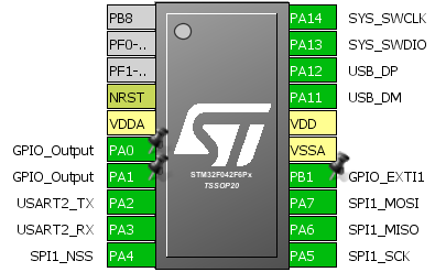
The existing project still builds fine for the new chip, because the device class (STM32F042x6) remains the same. If I still use the UART2 for SW tracing and 2 GPIO for test points, I wind up using almost all available pins, as you can see below.
Note that I still want to leave the PB8 for the DFU (device firmware upgrade) feature--which I will explore later. PF0/1 can potentially be used for additional GPIO since I do not use external oscillator (watch the BOM!). I will write the code to handle the button press with PB1 GPIO_EXTI handler later.
Sniffing the USB HID enumeration in Logic Analyzer
Since I did not yet modify the CubeMX generated custom USB HID source--which includes the USB device description table in Src/usb_desc.c or the custom HID configuration descriptor in the usbd_custom_hid_if.c, this FW should enumerate without a problem as VID=0x0483 and PID=0x5750, as hard coded in the beginning of the usbd_desc.c:
#define USBD_VID 1155
#define USBD_LANGID_STRING 1033
#define USBD_MANUFACTURER_STRING "STMicroelectronics"
#define USBD_PID_FS 22352
#define USBD_PRODUCT_STRING_FS "STM32 Custom Human interface"
#define USBD_SERIALNUMBER_STRING_FS "00000000001A"
#define USBD_CONFIGURATION_STRING_FS "Custom HID Config"
#define USBD_INTERFACE_STRING_FS "Custom HID Interface"
These strings are arranged in an array that is later indexed by both the device and the host.
USBD_DescriptorsTypeDef FS_Desc =
{
USBD_FS_DeviceDescriptor,
USBD_FS_LangIDStrDescriptor,
USBD_FS_ManufacturerStrDescriptor,
USBD_FS_ProductStrDescriptor,
USBD_FS_SerialStrDescriptor,
USBD_FS_ConfigStrDescriptor,
USBD_FS_InterfaceStrDescriptor,
};
When I connect the USB D+/D- pins to an old USB cable I sacrificed for the purpose and connect the "host" end (type A connector) to my laptop (burning out a USB 2.0 port in the trial-and-error stage; note to self for the future: ALWAYS use a cheapo hub to dork around with USB device!!), it tries to enumerate, as you can see in the properties discovered by the USBDeview program I downloaded to inspect all USB devices.
But I am curious what happened during enumeration, so in this section I will match up the Logic Analyzer's trace against my copy of
USB Complete, 4th Edition. You might want to skip to the next section if you don't care about how I teach myself the USB HID protocol.
I see the following packets on the wire:
- Reset: 11 ms (> 10 ms required by the 2.0 spec) of D+/D- both pulled low.
- 10 empty packets
- SYNC
- 8-bit PID. PID[0:3] = ~PID[4:7] for error checking. The 1st PID is SOF, which is followed by a 11-bit frame number (for FS). Note that the first frame number is random.
- CRC OK. CRC is 16-bit for data, and 5-bit for address and EP
- EOP: for FS, EP is D+ and D- both 0 for 2 bit widths.
- SETUP packet. Address = 0, endpoint = 0. This is the step 8 in USB Complete, 4th Edition, Enumeration chapter. 8th byte of the device descriptor contains the maximum packet size supported by the EP0
- DATA0
- Direction: device -> host
- Type: Standard
- Recipient = Device
- bRequest = 6 (GET_DESCRIPTOR)
- wIndex = 0
- wLength (11 bits) = 64
- Data CRC (16-bits)
- DATA1 (device --> host?). The following information was hard coded in USBD_FS_DeviceDesc
- bLength=18
- bDescriptorType=1 (DEVICE)
- bcdUSB = 0x200 (2.00)
- bDeviceClass = 0 (deferred to interface descriptors)
- bDeviceSubClass = 0
- bDeviceProtocol = 0
- bMaxPacketSize0 = 64. Windows host requests 64 bytes but after receveiving just one packet
- idVendor = 1155 (assigned to STM)
- idProduct = 22352
- bcdDevice = 0x200 (2.00)
- iManufacturer = 1.
- iProduct = 2
- iSerialNumber = 3
- bNumConfiguration = 1
- ACK
- IN, addr = 0, EP = 0
- device NACKs this IN
- Approximately 62 us later, host retries.
- Device replies back with the same data as in DATA1 in step 5 above.
- OUT, addr = 0, EP = 0. There should be a data that follows an OUT packet, but the only data I see is an empty DATA1, followed by an ACK from the device. Maybe this is just how the host and the device exchange ACK after an IN transaction?
- The hub resets the device. Reset lasted 11 ms.
- 16 SOFs, with 1 ms interval go unanswered.
- SETUP A=0, E=0
- Followed by DATA0 (requestType = 0, Request=5, SET_ADDRESS=4)
- And then an ACK
- It's bizarre why the host would follow up immediately with an IN packet for A=0, E=0, and 10 more SOFs go by. Maybe this is the "step 7 in the enumeration chapter of the USB Complete.
- Another SETUP, this time A=4, E=0, followed by DATA = GET_DESCRIPTOR (wLength = 18).
- The device responds with the same information as in step 5 above.
- Host sends another GET_DESCRIPTOR, but this time for CONFIGURATION[0].
- Host fires IN request, which the device NAKs. Host retries after 45 us, and this time, the device returns the information hard coded in the auto-generated usbd_customhid.c USBD_CUSTOM_HID_CfgDesc:
- the max power for the configuration = 100 mA
- Descriptor type = 0x04 (interface), interface number = 0, alternate setting = 0, interface class = 3 (HID), subclass = 0 (none), protocol = 0, iInterface = 0, bLength=9
- DescriptorType = 0x21 (HID). HID version = 0x0111 (1.11), country = not supported, bNumDescriptor = 1, HID report descriptor.
- 1 IN interrupt report, and 1 OUT interrupt report. wMaxPacketsize = 2 bytes (I don't know why we use different defines than the USBD_CUSTOM_HID_REPORT_DESC_SIZE seen earlier; keeping track of yet another 2 defines CUSTOM_HID_EPOUT_SIZE and CUSTOM_HID_EPIN_SIZE just seems like a chore). Polling interval both 20 ms.
- OUT (A=4, EP=0), empty DATA
- SETUP, GET_DESCRIPTOR for STRING descriptor, index 3, language = English
- IN: answered by NAK
- 80 us later, SOF, IN, with DATA this time, for the string descriptor at index (3+1) in the FS_Desc string array shown above.
- Why this is followed immediately by an unnecessary OUT with empty DATA, I don't understand.
- SETUP/GET_DESCRIPTOR for the string at string array index 0. This is answered with IN, wLANGID=1033, which is at array index 1:SETUP/GET_DESCRIPTOR for string array index 2, wIndex=1033 (language = English).
- SETUP/GET_DESCRIPTOR for string index 2, which is answered by the string at the array index 3 above (product)
- SETUP-GET_DESCRIPTOR for DEVICE_QUALIFIER[0], which is answered by a STALL, which means the device does not support this request.
- After 16 empty SOF/ACK exchange, the host seems to recover, and sends SETUP-GET_DESCRIPTOR for DEVICE[0]. The device answers with the same information as in step 5 above.
- SETUP-GET_DESCRIPTOR for CONFIURATION[0]. As with all other GET_DESCRIPTOR, the host initiates IN transaction almost right away (14 us), and the device NAKs the first IN. The content of the CONFIGURATION[0] is the same as in step 14 above.
- CONFIGURATION[0] IN transaction is repeated AGAIN right away--why??
- SETUP-SET_CONFIGURATION(0), which the device ACKs right away. Note that this device only has 1 configuration
- IN is NAKed, and then answered with an empty DATA
- SETUP-HID SET_IDLE(duration = indefinite, report ID = 0). This is to save BW by limiting the reporting frequency of an interrupt IN EP when the data hasn't changed since the last report.
- IN-empty data
- SETUP-GET_DESCRIPTOR[0] is answered by "Unknown main item (0); end collection". The report descriptor is hard-coded in CUSTOM_HID_ReportDesc_FS discussed earlier.
Maybe the "end collection" tells the Windows host that there is no more to be learned, so it can loads the device driver. But an ill-formed HID report descriptor (the 2 bytes shown in the previous section) prevents successful enumeration.
My own HID report descriptor
So I tried designing my own HID report descriptor using the USB-IF's "HID DT (descriptor tool)", like this:
__ALIGN_BEGIN static uint8_t CUSTOM_HID_ReportDesc_FS[USBD_CUSTOM_HID_REPORT_DESC_SIZE] __ALIGN_END =
{
/* USER CODE BEGIN 0 */
0x06, 0x00, 0xFF,//USAGE_PAGE (Vendor Defined Page 1) // 3 B
0x09, 0x00, //USAGE (Undefined) // 5 B
0xA1, 0x01, //COLLECTION (Application) // 7 B
0x75, 0x08, // REPORT_SIZE (8) // 9 B
0x95, 0x01, // REPORT_COUNT (1) // 11B
0x92, 0xA3, 0x01,// OUTPUT (Cnst, Var, Abs, NPrf, Vol, Buf)// 14B
/* USER CODE END 0 */
0xC0 /* END_COLLECTION */
}
CubeMX unfortunately does not bracket the definition of USBD_CUSTOM_HID_REPORT_DESC_SIZE in "USER CODE" markers so that I have to keep changing the USBD_CUSTOM_HID_REPORT_DESC_SIZE every time I generate the code. With this descriptor, the HID device enumerates, as you can see in the Device Manager --> HID view:
Let's see if I can talk to the device from the development PC. But first, a little detour about USB suspend, because I noticed that the USB port gets powered off immediately after enumeration--I
think that's how it is supposed to be. Strangely, the keep alive messages (SYNC) do not cease on the wire?!
Bus powered device
In usbd_conf.h, the CubeMX hard codes the self powered setting, just like it hard codes the custom HID report description size.
#define USBD_SELF_POWERED 1
#define USBD_CUSTOM_HID_REPORT_DESC_SIZE 2 //should be 15; see above
Both hard-coded settings are inappropriate for me, and the fact that I cannot override them is annoying. Nevertheless, let's fix them both
USB SUSPEND
After the initial enumeration, there is no activity on the bus, so the device must enter SUSPEND state (after 3 ms without a SYNC). How can I tell whether the ST USB middleware is entering SUSPEND? When I search for "SUSPEND" in the CubeMX generated code, I found a function USB_LL_Suspend() that informs the USB library that the core is entering the suspend mode. This function is called right before the STM32 is put into stop mode, as you can see here:
void HAL_PCD_SuspendCallback(PCD_HandleTypeDef *hpcd)
{
/* Inform USB library that core enters in suspend Mode */
USBD_LL_Suspend(hpcd->pData);
/*Enter in STOP mode */
/* USER CODE BEGIN 2 */
if (hpcd->Init.low_power_enable)
{
/* Set SLEEPDEEP bit and SleepOnExit of Cortex System Control Register */
SCB->SCR |= (uint32_t)((uint32_t)(SCB_SCR_SLEEPDEEP_Msk | SCB_SCR_SLEEPONEXIT_Msk));
}
/* USER CODE END 2 */
}
Unfortunately, CubeMX hard codes low_power_enable to 0 in USBD_LL_Init() as you can see here:
hpcd_USB_FS.Init.low_power_enable = DISABLE;
So I will have to a modified version of usbd_conf.c USBD_LL_Init() if I want to put the uC to deep sleep, but note that the CubeMX code does NOT turn off the power domains before going to sleep, as shown in the HAL_PWR_EnterSTOPMode(PWR_LOWPOWERREGULATOR_ON, PWR_STOPENTRY_WFI) I currently use:
tmpreg = PWR->CR;
/* Clear PDDS and LPDS bits */
tmpreg &= (uint32_t)~(PWR_CR_PDDS | PWR_CR_LPDS);
/* Set LPDS bit according to Regulator value */
tmpreg |= Regulator;
But I have a suspicion that the suspend callback is not even getting called.
Windows app to test drive the bus-powered custom HID device
In
USB Complete, 4th Edition, I did not understand why Jan Alexson talked about the managed and unmanaged functions--until I realized that MSFT does not offer .NET Windows USB API. Of course,
someone would have already made a .NET library to access the Windows HID API and I can just use it. I unzipped csharp-usb-hid-driver (GPL3 license), to find the project USBHIDDRIVER in its own folder. I created my own C# console application project (named WinCustomHID, which also creates a solution WinCustomHID.sln) and added USBHIDDRIVER as another project in my own solution (I was forced to upgrade the USBHIDDRIVER project). My own project will need a reference to the USBHIDDRIVER project (right click on the project --> Add --> Reference --> Projects --> USBHIDDRIVER).
The usage is simple: create an interface to the device, connect, and start writing, as shown in this example:
using USBHIDDRIVER;
namespace WinCustomHID
{
class Program
{
static void Main(string[] args)
{
const string vid = "vid_0483", pid = "pid_5750";
USBInterface usb = new USBInterface(vid, pid);
if (!usb.Connect()) {
Console.WriteLine("Could not connect to {}/{}", vid, pid);
}
byte[] command = { 0x42 };
usb.write(command);
Console.WriteLine("Done");
// Have to comment out the usbThread in the lib to avoid crash!
usb.Disconnect();
}
}
}
The documentation says that write() can handle up to 64 bytes, but I found that strange, given that my HID report descriptor explicitly stated that it can only handle 1 byte. When I browsed the code, I found that "64 byte" was hard-coded--maybe because that is the maximum size of a HID report.
Writing to a custom HID on Android
The device, running the SAME FW, is NOT enumerating on Android. But MCP2210 does enumerate to Android, so the problem must be in either my device or the FW...
Waking up the host
In
USB Complete, 4th Edition, the only clue on how to remote wakeup the host from a device I could find was in
Resuming Communications section:
The device ... indicates ... in ... bmAttributes. The host enables remote wakeup by sending a Set Port Feature(DEVICE_REMOTE_WAKEUP) request to the hub port that is the device's link partner. A suspended device with remote wakeup enabled can request to resume communications by driving the upstream bus in the Resume state for 1-15 ms.
To "drive the upstream bus" (HW action), I need to follow the STM32F0 reference manual's USB chapter:
Resume sequence can be started by setting the RESUME bit in the USB_CNTR register to ‘1 and resetting it to 0 after an interval between 1ms and 15ms (this interval can be timed using ESOF interrupts, occurring with a 1ms period when the system clock is running at nominal frequency).
The FW will need to set the
USB_CNTR_RESUME bit in
hpcd->Instance->CNTR = wInterrupt_Mask after waking up from EXTI.